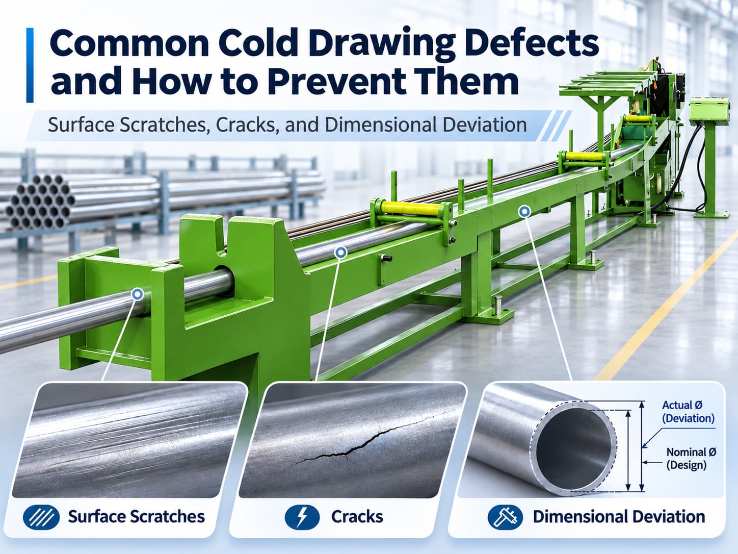
Surface scratches, cracks, and dimensional deviation are common defects in the cold drawing process. They can result from worn drawing dies, inadequate lubrication, excessive reduction per pass, or inconsistent incoming material.
These defects affect surface finish, dimensional accuracy, and material integrity, potentially increasing scrap rates and production costs.
To prevent cold drawing defects, manufacturers should identify the defect pattern, inspect the relevant process conditions, and correct the root cause before continuing production.
This guide explains the causes of three common cold drawing defects, practical troubleshooting methods, and how suitable processing equipment can support consistent production quality.
1. Common Cold Drawing Defects at a Glance
Cold drawing defects can generally be identified through visual inspection, dimensional measurement, and material testing. The following table summarizes three common problems and the factors manufacturers should investigate first.
| Defect | Typical Symptoms | Main Causes |
|---|---|---|
| Surface Scratches | Longitudinal marks, grooves, surface scoring | Poor lubrication, die damage, contamination |
| Cracks | Surface splits, internal cracking | Excessive reduction, insufficient ductility, material defects |
| Dimensional Deviation | Diameter variation, ovality, inconsistent wall thickness | Die wear, misalignment, incoming material variation |
Different defects may share contributing factors. However, manufacturers should avoid changing multiple process parameters before identifying the most likely cause.
2. Surface Scratches: What Causes Them and How Can They Be Prevented?
Surface scratches typically appear as lines or grooves along the drawing direction. They may affect product appearance and create problems during subsequent machining, coating, or finishing.
Common Causes
Poor Lubrication
Insufficient or uneven lubrication increases friction between the workpiece and drawing die, potentially causing surface scoring.
Damaged Drawing Dies
Scratched or worn die surfaces may transfer repeated marks onto the drawn material.
Material Contamination
Scale, metal particles, or other debris can become trapped between the material and die, damaging the surface during drawing.
How to Prevent Surface Scratches
- Check lubricant coverage, suitability, and cleanliness.
- Inspect drawing dies for scoring, wear, or surface damage.
- Clean incoming material before drawing.
- Check material guides and handling equipment for contact damage.
3. Cracks: Why Do They Occur During Cold Drawing?
Cracks occur when the material cannot accommodate the deformation or stress imposed during processing. They may develop on the surface or internally, depending on the material and drawing conditions.
Unlike superficial scratches, cracks can compromise material integrity and lead to product rejection.
Common Causes
Excessive Reduction per Pass
A large cross-sectional reduction can increase drawing stress beyond the material's available deformation capacity, raising the risk of cracking.
Insufficient Material Ductility
Cold working can increase hardness and reduce the remaining ductility of many metals. If deformation accumulates over multiple passes, additional drawing may cause failure.
Unsuitable Die Geometry or Material Condition
Improper die geometry can create unfavorable material flow and stress distribution. Pre-existing material defects may also develop into visible cracks during drawing.
How to Prevent Cracks
- Establish a suitable reduction schedule for the material and target dimensions.
- Inspect incoming material for seams, cracks, and other defects.
- Verify that die geometry matches the drawing requirements.
- Consider intermediate annealing when required by the material's work-hardening behavior.
- Investigate abnormal drawing-force increases before continuing production.
How Is Reduction per Pass Calculated?
Reduction in area is calculated using:
- A0: Original cross-sectional area
- Af: Final cross-sectional area
- R: Percentage reduction in area
For tube drawing, both the outside and inside dimensions must be considered when calculating the metal cross-sectional area.
4. Dimensional Deviation: What Causes Inconsistent Drawing Accuracy?
Dimensional deviation occurs when the finished material fails to meet specified tolerances for diameter, cross-sectional geometry, or wall thickness.
This is particularly important for precision bars and tubes used in machining, assembly, and industrial components.
Common Causes
Die Wear
Drawing die wear may gradually change the effective forming dimensions, resulting in size variation during production.
Tooling Misalignment
Misalignment between the drawing die, feeding direction, and internal tooling can cause uneven deformation or inconsistent tube wall thickness.
Inconsistent Incoming Material
Variation in initial material dimensions, geometry, or properties can affect the finished product even when machine settings remain unchanged.
How to Improve Dimensional Accuracy
- Inspect drawing dies and verify their dimensions.
- Maintain proper die and feeding-axis alignment.
- Measure incoming material before drawing.
- Monitor drawing conditions and investigate abnormal changes.
- Measure finished dimensions at defined production intervals.
For tube drawing, outside diameter alone is not sufficient. Wall thickness, ovality, and other specified geometric tolerances may also require inspection.
Is Dimensional Accuracy the Same as Straightness?
No. Dimensional accuracy describes the size and geometry of the cross-section, while straightness describes deviation from a straight longitudinal axis.
A product can meet its diameter tolerance but still require downstream straightening.
For a detailed explanation of how drawing, annealing, and straightening conditions interact, read Why Do Tubes Bend Again After Annealing and Straightening?
5. Cold Drawing Troubleshooting Checklist
When a defect appears during production, the first step is to identify its pattern and determine which process condition should be inspected.
The following checklist helps operators prioritize troubleshooting without making unnecessary equipment adjustments.
| Observed Problem | First Inspection Priority | Suggested Action |
|---|---|---|
| Continuous longitudinal scratches | Die surface | Check for scoring or damage |
| Random surface marks | Lubrication and material cleanliness | Remove contaminants and inspect contact points |
| Cracks after drawing | Reduction schedule and material condition | Review reduction per pass and ductility |
| Repeated surface splits | Incoming material | Inspect for pre-existing defects |
| Gradual diameter variation | Die wear | Measure and inspect die dimensions |
| Uneven tube wall thickness | Tooling alignment and incoming tube geometry | Check die, mandrel, and starting dimensions |
| Inconsistent dimensions between batches | Incoming material and process records | Compare material specifications and drawing parameters |
What Production Data Should Be Recorded?
For recurring defects, manufacturers should document:
- Material grade and incoming dimensions
- Die identification and condition
- Reduction per pass
- Lubrication conditions
- Drawing speed and available drawing-force data
- Inspection results and defect location
Recording this information helps manufacturers distinguish isolated material problems from recurring tooling or process issues.
6. How Can the Right Equipment Improve Cold Drawing Quality?
Suitable cold drawing equipment supports stable material feeding, controlled drawing conditions, and repeatable production.
However, equipment selection should be based on material characteristics, dimensional requirements, reduction needs, and production volume.
Cold Drawing Machines
HOREN's Cold Drawing Machines are designed for processing metal bars, tubes, and wires.
The product range includes cold bar drawing machines and tube drawing machines, with different drawing configurations available for specific production requirements.
A properly selected drawbench provides the required drawing capability, while dimensional accuracy and surface quality also depend on suitable dies, lubrication, and incoming material.
Automatic Cold Drawing Machines
For manufacturers requiring higher-volume production, HOREN provides Automatic Cold Drawing Machines .
The HS series integrates material loading, feeding, a hydraulic push pointer, drawing, and discharging operations through PLC-controlled automation.
These systems are particularly relevant to suitable bar drawing applications involving round, square, and hexagonal profiles.
Automation helps reduce repetitive manual handling and supports production consistency, but it does not independently eliminate defects caused by unsuitable tooling or material conditions.
Multi-Roller Straightening Machines
After cold drawing, some products may require straightening to meet final straightness requirements.
HOREN's Multi-Roller Horizontal Straightening Machines provide downstream correction for suitable tubes, bars, and wires.
Straightening should be treated as a separate finishing operation rather than a solution for surface scratches, cracking, or out-of-tolerance cross-sectional dimensions.
Which Equipment Should You Consider?
| Production Requirement | Recommended Equipment |
|---|---|
| Controlled dimensional reduction of metal bars or tubes | Cold Drawing Machine |
| Higher-volume production with automated material handling | Automatic Cold Drawing Machine |
| Improving straightness after drawing or other processing stages | Multi-Roller Horizontal Straightening Machine |
Before selecting equipment, manufacturers should confirm material grade, initial and final dimensions, required tolerances, production capacity, and downstream processing requirements.
7. Frequently Asked Questions
Can cold drawing defects be prevented by reducing drawing speed?
Not always. Lower drawing speed may help under certain friction, lubrication, or temperature conditions, but it cannot correct damaged dies, unsuitable reduction schedules, or defects already present in the material. The root cause should be identified before adjusting speed.
When should manufacturers replace a drawing die?
A drawing die should be inspected when repeated surface marks, abnormal drawing-force changes, or dimensional drift appear. Replacement or reconditioning depends on the extent of wear, the die's condition, and whether it can still meet the required production tolerances.
Improve Cold Drawing Quality with HOREN Industrial
Preventing cold drawing defects requires suitable tooling, consistent process control, and equipment matched to the material and production requirements.
HOREN Industrial provides cold drawing machines, automatic cold drawing machines, and multi-roller straightening machines for metal processing applications.
Whether you are planning a new production line or improving an existing cold drawing process, our team can help evaluate your equipment requirements based on material specifications, processing conditions, and production capacity.
Explore Our Equipment Contact HOREN